
CHASSIS FRAME AND BODY
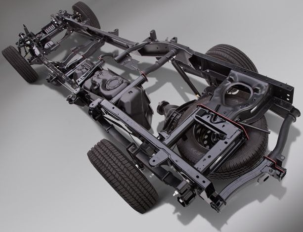
Introduction of Chassis Frame: Chassis is a French term and was initially used
to denote the frame parts or Basic Structure of the vehicle. It is the back bone
of the vehicle. A vehicle with out body is called Chassis. The components of
the vehicle like Power plant, Transmission System, Axles, Wheels and Tyres,
Suspension, Controlling Systems like Braking, Steering etc., and also electrical
system parts are mounted on the Chassis frame. It is the main mounting for all
the components including the body. So it is also called as Carrying Unit.
Layout of Chassis and its main Components:

The following main components of the Chassis are
1. Frame: it is made up of long two members called side members
riveted together with the help of number of cross members.
2. Engine or Power plant: It provides the source of power
3. Clutch: It connects and disconnects the power from the engine fly
wheel to the transmission system.
4. Gear Box
5. U Joint
6. Propeller Shaft
7. Differential
FUNCTIONS OF THE CHASSIS FRAME:
1. To carry load of the passengers or goods carried in the body.
2. To support the load of the body, engine, gear box etc.,
3. To withstand the forces caused due to the sudden braking or
acceleration
4. To withstand the stresses caused due to the bad road condition.
5. To withstand centrifugal force while cornering
TYPES OF CHASSIS FRAMES:
There are three types of frames
1. Conventional frame
2. Integral frame
3. Semi-integral frame
1. Conventional frame: It has two long side members and 5 to 6 cross
members joined together with the help of rivets and bolts. The frame sections
are used generally.

a. Channel Section - Good resistance to bending
b. Tabular Section - Good resistance to Torsion
c. Box Section - Good resistance to both bending and
Torsion
2. Integral Frame: This frame is used now a days in most of the cars. There is
no frame and all the assembly units are attached to the body. All the
functions of the frame carried out by the body itself. Due to elimination of
long frame it is cheaper and due to less weight most economical also. Only
disadvantage is repairing is difficult.

3. Semi - Integral Frame: In some vehicles half frame is fixed in the front end
on which engine gear box and front suspension is mounted. It has the
advantage when the vehicle is met with accident the front frame can be
taken easily to replace the damaged chassis frame.

This type of frame is used in FIAT cars and some of the European and American cars.
VARIOUS LOADS ACTING ON THE FRAME:
Various loads acting on the frame are
1. Short duration Load - While crossing a broken patch.
2. Momentary duration Load - While taking a curve.
3. Impact Loads - Due to the collision of the vehicle.
4. Inertia Load - While applying brakes.
5. Static Loads - Loads due to chassis parts.
6. Over Loads - Beyond Design capacity.
THE DIFFERENT BODIES USED IN AUTOMOBILES:
The Automobile bodies are divided in two groups


According to Chassis design the body can divided into
1. Conventional Type
2. Integral Type
3. Semi- Integral Type
According to other usage:
1. Light vehicle Bodies - cars, jeeps
2. Heavy vehicle Bodies – Busses, Lorries
3. Medium vehicle Bodies - Vans, Metadoors
REQUIREMENTS OF BODIES FOR VARIOUS TYPES OF VECHILE:
The body of the most vehicle should fulfill the following requirements:
1. The body should be light.
2. It should have minimum number of components.
3. It should provide sufficient space for passengers and luggage.
4. It should withstand vibrations while in motion.
5. It should offer minimum resistance to air.
6. It should be cheap and easy in manufacturing.
7. It should be attractive in shape and colour.
8. It should have uniformly distributed load.
9. It should have long fatigue life
10.It should provide good vision and ventilation.
STEERING SYSTEM

Introduction: This system provides the directional change in the movement of
an Automobile and maintain in a position as per the driver’s decision without
much strain on him.
REQUIREMENTS OF STEERING SYSTEM:
a. It must keep the wheel at all times in to rolling motion with out
rubbing on the road.
b. This system should associate to control the speed.
c. It must light and stable.
d. It should also absorb the road shocks.
e. It must easily be operated with less maintenance.
f. It should have self-centering action to some extent.

Functions of Steering System:
1. It helps in swinging the wheels to the left or right.
2. It helps in turning the vehicle at the will of the driver.
3. It provides directional stability.
4. It is used to minimize the tyre wear and tear.
5. It helps in achieving self-centering efforts.
6. It absorbs major part of the road shocks.
Main Components of Steering System:

The following are the main components of steering system are
1. Steering Wheel
2. Steering column or shaft
3. Steering Gear
4. Drop Arm or Pitman Arm
5. Drag Link
6. Steering Arm
7. Track-Arms
8. Track Rod or Tie-Rod
9. Adjusting Screws
Types of Steering Gear Boxes:
1. Worm and Wheel Steering Gear.
2. Worm and Roller Steering Gear.
3. Re-circulating Ball type Steering Gear.
4. Rack and Pinion type Steering Gear.
5. Cam and Roller Gear type Steering Gear.
6. Cam and Peg Steering Gear.
7. Cam and Double lever Steering Gear.
8. Worm and Sector Type Steering Gear.
Functions of Steering Gear Box:
1. It converts the Rotary movement of the steering wheel in to the
angular turning of the front wheels.
2. It also multiplies drivers efforts and give MEHANICAL ADVANTAGE.
1.Worm and Wheel Type: This type of steering gear has a square cut screw
threads at the end of the steering column; which forms a worm, at the end of
it a worm wheel is fitted and works rigidly with it. Generally covered shaft is
used for the worm wheel. The worm wheel can be turned to a new position
the drop arm can be readjusted to the correct working position.

2. Re-circulating Ball Type: In this type of gear box the endless chain of balls
are provided between the worm and nut members. The nut form a ring of
rack having an axial movement.

So that the sector on the rocker shaft racks,
the balls roll continuously between the worm and nut. Being provided with
return chambers at the ends of the worm. This method reduces friction
between worm and nut members. This type of steering gear is used for heavy
vehicles.

3. Rack and Pinion Type: This is common manual type of steering gear box
is used in most of the vehicles. In this type of steering a pinion is provided the
bottom end of the steering column. The teeth of the pinion wheel in mesh
with corresponding teeth provided on the rack, the end of which are

connected to the stub axle through the rod. The rotating motion of the
pinion operates the rack in FORE and AFT direction which in turn operates the
stub axle.

4. Cam and Lever Type: The cam and lever steering uses one or two lever
studs fitted in taper roller bearing. When the worm in the form of helical
groove rotates the stub axle and it also rotates along with it. This imports a
turning motion to the drop arm shaft.

5. Worm and Sector Type: In this type the worm on the end of the steering
shaft meshes with a sector mounted on a sector shaft. When the worm is
rotated by rotation of the steering wheel, the sector also turn rotating the
sector shaft. Its motion is transmitted to the wheel through the linkage. The
sector shaft is attached to the drop arm or pitmen arm.

Power Steering: Power steering reduces much strain on the part of the driver
while negotiating sharp curves. It makes easy to turn sharp corners. It is usually arranged to be operative when the effort of steering wheel exceeds a predetermined value. It is fitted on heavy commercial vehicles and medium
cars.
Steering Linkages: Steering Linkage is a connection of various links between
the steering gear box and the front wheels. The motion of the pitman arm
and steering gear box is transferred so the steering knuckles of the front
wheels through the steering linkages. The swinging movement of the pitman
arm from one side to the other side gives angular movement to the front
wheel through the steering linkages.
Types of steering Linkages:
1. Conventional steering Linkage.
2. Direct cross type steering linkage
3. Three piece steering linkage
4. center arm steering linkage
5. Relay type steering linkage.
Slip Angle: The angle between direction of the motion of the vehicle and the
center plane of the tyre is known as Slip Angle. It ranges from 8º to 10º.
Under steer: When the front slip angle is greater than that of rear, the vehicle
tends to steer in the direction of side force. Then it is known as under steer. This
provides greater driving stability, especially when there is a side wind.
Over Steer: When the rear slip angle is greater than that of front slip angle,
the vehicle tends to mover away from the direction of center path. This is
known as over stear. This is advantageous when the vehicle moving on the road having many bends curves.
Steering Gear Ratio or Reduction Ratio: It has been defined as the “ number
of turns on the steering wheel required to produce on turn of steering gear
cross shaft to which the pitman arm is attached. Generally it varies between
14'.1 and 24'.1.
Turning Radius: It is the radius of the circle on which the outside front wheels
moves when the front wheels are turned to their extreme outer position. This
radius is 5 to 7.5 m for buses and trucks.Wheel Alignment: It returns to the positioning of the front wheels and steering
mechanism that gives the vehicle directional stability, reduce the tyre wear
to a minimum.
Factors effects the wheel alignment:
1. Factors pertaining to wheel:- a. Balance of wheels(Static and Dynamic)
b. Inflation of tyre.
c. Brake adjustments.
2. Steering Linkages.
3. Suspension System
4. Steering Geometry –a. caster b. camber c. king pin inclination d. toe-in
and toe-out etc.,
Steering Geometry: It refers to the angular relationship between the front
wheels and parts attached to it and car frame.
The steering Geometry includes
1. Caster angle
2. Camber angle
3. King-pin inclination
4. toe-in
5. toe-out etc.,
Caster Angle: This is the angle between backward or forward tilting of the
king pin from the vertical axis at the top. This is about 2º to 4º. The backward
tilt is called as positive caster. The forward tilt is called negative caster.
Camber: The angle between wheel axis to the vertical line at the top is
called camber angle. It is approximately ½º to 2º. King-pin inclination: It is the angle between vertical line to the king pin axis.
The inclination tends to keep wheels straight ahead and make the wheels to
get return to the straight position after completion of a turn. The inclination is
normally kept 7º to 8º.

Toe-in: It is the amount in minimum at the front part of the wheel points
inwards approximately 3 to 5 mm. It prevents side slipping excessive tyre
wear, proper rolling of front wheels and steering stability.

Toe-out: It is the difference in angles between two front wheels and vehicle
frame during turning. It is used to prevent dragging of tyre during turn.
Reversible steering: When the deflection of road wheels is transmitted
through the steering wheel to road surface, the system is called Reversible.
If every imperfection of road surface causes the steering to rotate, it
causes much strain on the part of the driver to control the vehicle. It causes
much strain on the part of the driver to control the vehicle. There fore such of
the reversibility is not desired. But, some degree of reversibility desired, so that
the wheel becomes straight after taking a curve.
Irreversible steering: If the front road wheels does not transfer any deflection
to the steering which is called irreversible steering. After negotiating a curve
and the steering wheel not returned easily, there causes the production of un due stresses on the steering mechanism, therefore some degree of
irreversible also desired.
Steering Mechanism: There are two types of steering gear mechanisms
1. Davis Steering gear 2. Ackermann Steering gear
1. Davis Steering Gear: The Davis Steering gear has sliding pair, it has more
friction than the turning pair, there fore the Davis Steering Gear wear out
earlier and become inaccurate after certain time. This type is mathematically
Accurate.
The Davis gear mechanism consists of cross link KL sliding parallel to
another link AB and is connected to the stub axle of the two front wheel by
levers ACK and DBK pivoted at A and B respectively. The cross link KL slides in
the bearing and cross pins at its ends K and L. The slide blocks are pivoted on
these pins and move with the turning of bell crank levers as the steering
wheel is operated. When the vehicle is running straight the gear is said to be
in its mid-position. The short arms AK and BL are inclined an angle 90 t α to
their stub axles AC and BD respectively. The correct steering depends upon
the suitable selection of cross arm angle α, and is given by
Tan α = b/2l Where b= AB = distance between the pivots of front axle.
l=wheel base
2. Ackermann Steering System: It has only turning pair. It is not
mathematically accurate except in three positions. The track arms are made
inclined so that if the axles are extended they will meet on the longitudinal
axis of the car near rear axle. This system is called ackermann steering.
0 comments:
Post a Comment