BRAKING SYSTEM

INTRODUCTION:
Braking is the mechanism in the motor vehicle which is used
to slowing down and stopping the vehicle to rest in the shortest possible
distance.
Principle of Braking system: While operating the braking system the KINETIC
ENERGY of moving vehicle is converted in to HEAT ENERGY.
Functions of Brakes: Brakes have the following functions.
1.It is used to stop the vehicle.
2.It is used to control the speed where and when required.
3.It is used to control the vehicle while descending along the slope.
4.To park the vehicle and held it in stationary position without the presence of
Driver.
Requirements of Automobile Brakes:
1.It should work efficiently irrespective of road condition and quality.
2.The retardation must be uniform throughout its application.
3.The pedal effort must be within the convenient capacity of the driver.
4.It must be reliable and should not be effected by heat water and dust.
5.It should be in minimum weight.
6.It should have long life.
7.It should be easy to maintain and adjust.
8.Noise and vibrations are to be minimum.
9.There should be provision for secondary brake or parking brake.
Stopping distance and Braking efficiency:
For practical measure for braking efficiency that of the minimum
distance in which it can be brought in to rest after the brake is applied.
The stopping distance depends upon
1.Grip between the tyre and road surface.
2.Tyre tread condition.
3.Tyre inflation.
4.Nature of road surface.
The stopping distance is calculated by
D=kv2
Where d=stopping distance in kilometers.
K=Constant depending upon the road and tyre inflation.
V=velocity of the vehicle per hour.
The value of k is 1/25 for 4 wheel braking system.
1/12 for 2 wheel braking system.
The braking efficiency is calculated by the equation:
η=V
2
/3D where v=velocity of the vehicle
d=stopping distance.
Condition of Brake Braking efficiency in %
1.Perfect 90%
2.Excellent 77%
3.Good 70%
4.Fair 60%
5.Poor 50%
6.Bad 37%
7.Very bad 30%
Below Fair is very danger.
Classification of Brakes: The following are the classifications of Brakes:
1.By method of power
a) Mechanical brakes
b) Hydraulic brakes
c) Vacuum brakes
d) Air brakes
e) Electrical brakes
f) Magnetic brakes
g) Air assisted hydraulic brakes
2.By method of application:
a) Service or foot brakes
b)Parking or hand brakes
3.By method of operation:
a) Manual
b) Servo
c) Power operation
4. By method of Braking contact
a. Internal Expanding Brakes
b. External Contracting Brakes.
5. By Method of Applying Brake force:
a. Single Acting Brakes.
b. Double Acting Brakes.
Types of Mechanical Brakes:
a. Drum Brakes (Internal Expanding or External Contracting)
b. Disc Brakes (Single or Two caliper)
Drum Brakes:

Construction: The main components of drum brakes are
1. Brake drum
2. Back plate
3. Brake shoes
4. Brake Liners
5. Retaining Springs
6. Cam
7. Brake Linkages
In this system the wheel is attached to drum. There are brake shoes used to
contact the rotating drum for braking operation. The shoes provide lining on
their outer surface. The cam is used to lift the brake shoes at one end, other
end is connected by some method so as to make as the brake sleeve come
into contact in the brake drum. The retaining spring is provided for bringing
the brake shoes back to its original position, after releasing the brake pedal.
All these parts are fitted in the back plate and enclosed with brake drum. This
system .

through linkages, there by coming in frictional contact with the rotating drum.
As soon as the brake pedal is released the retaining springs help the brake
shoes to brought back and release the brakes.
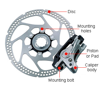
2. Disc brakes:

There are two types of disc brakes:
1. Spot Type
a. Swinging Caliper Type
b. Sliding caliper type
2. Clutch Type
Construction: The discs are made of gray cast Iron. The brake pressure in
case of disc brakes have to be much lighter than the drum brakes.
It consists of rotating disc and two friction pads which are actuated by
the four hydraulic wheel pistons contain in two halves of an assembly is called
a caliper. The caliper assembly is secured to the steering knuckle in a front
wheel brakes. The road wheel is fashioned to the outer surface of the disc.
The friction pads rides freely on each side of the discs. They are in position
being the hydraulic systems.
Working:
When the brakes is applied hydraulic pressure is supply to the fluid inlet
tube, due to which the wheel cylinder piston force the friction pads against
the rotating disc. In the released piston, the spring hold the piston pads so
that they maintain contact with disc surface.
Construction and Working of Hydraulic systems:
Hydraulic brakes make used of hydraulic pressure to force brake shoes
out words against the brake drum based on PASCAL’S LAW.
Construction: The main components of the system is
1. Master Cylinder 2. Wheel Cylinder

The figure shows the master cylinder is connected by tubing to the
wheel cylinder, at each of the four wheels. The system is filled with the liquid
under light pressure when the brake is not in operation. The brake fluid
generally a mixture of glycerin and alcohol or caster oil, denatured alcohol
and some additives.
The brakes shoes which are mounted on the inner side of the brake
drum and do not rotate. The brake liners are fitted on the outer surface of the brake shoes. The brake pedal is connected to the master cylinder piston by
means of a piston rod.
Working: When the brake pedal is pressed the piston is forced in to the
master cylinder, the hydraulic pressure is applied equally to all wheel
cylinders. The pistons in the wheel cylinders pushed outwards against the
brake drum.
When the driver release the brake pedal, the piston in the master
cylinder returns back to its original position due to the return spring pressure.
Thus the pistons in the wheel cylinder come back in its original inward position.
Thus the brakes are released
Construction and working of Master Cylinder

Master Cylinder: The Master Cylinder is the heart of the hydraulic brake
system. It consists of two main chambers. The fluid reservoir which contains
the fluid to supply to the brake system, and the compression chamber in
which the piston operates. The reservoir supplies fluid to the brake system
through two ports. The larger port is called the filler or intake part and is
connected to the hollow portion of the piston between the primary and
secondary cups which act as piston seals. The smaller port is called the relief,
bypass or compensating port which connects the reservoir directly with the
cylinder and lines when the piston is in the released position.
When the brake pedal is depressed, the master cylinder piston moves
forward to force the liquid under pressure into the system. The relief port is
sealed out of the system. The liquid pressure is conducted to the wheel
cylinders, where it forces the wheel cylinder pistons out wards. These pistons
force the brake shoes out against the brake drums When brake pedal is released, the return spring quickly forces the master cylinder piston back against the piston stop. Because the fluid in the
lines returns rather slowly, a vacuum tends to form in the cylinder in front of
the piston. This causes the primary cup to collapse to allow the liquid to flow
from the reservoir through the filter port past the piston to fill the vacuum.
Construction and working of Wheel Cylinder

WHEEL CYLINDER: Wheel cylinder is the second important hydraulic brake
system. It consists of two pistons which can move in opposite directions by the
fluid pressure. It is rigidly mounted on the brake shield or backing plate. The
boots protect the cylinders from foreign substances. Bleeder valves are
provided in the cylinder to permit air and liquid to be pumped out of the
system during of the bleeding operation .
Piston cup fits tightly in the cylinder against each piston and seal the
mechanism against leakage of the brake fluid. A Spring serves to hold the
cups against the piston when the pressure is decreased.
When the brakes are applied the brake fluid enters the cylinder from a
brake line connection inlet between the two pistons. It causes to force out
the two pistons in opposite directions. This motion is transmitted to the brake
shoe. Directly or through links force them against the brake drum, thus
applying the brake.
Construction and working of Tandem master Cylinder
In this master cylinder there are two pistons in the and hydraulic
pressure developed in two chambers one for the front left, and rear right
brakes and other for the front right and rear left brakes.
In tandem master cylinder one cylinder operates the front brakes while
the other cylinder operates the rear brakes.
Construction and working of Air Brake System:
The air brake system consists of two-stage air-compressor driven by the
crankshaft or gearbox shaft. It takes air from atmosphere, compresses it and
delivers to the air reservoir through un-loader valve. Where the pressure of
the reservoir reaches the maximum degree, the un- loader valve opens to the
atmosphere. Then the compressed air is directed in to the atmosphere
directly.
Each of the four wheels fitted with brake chambers consists of a
diaphragm, and which the air pressure is applied and pushes it. This force
operates the cam actuating lever and applies the brake. Each of the brake
chamber is connected to the brake pedal, and air filter is also fitted between
the brake valve and reservoir.
Working: When the brake pedal is pushed the brake valve opens and
compressed air is allowed in to the brake chamber. The brake valve consists
of three passages.
1. Air intake 2. Exhaust 3. Brake chamber
When the brake pedal is pressed the exhaust passage will be closed
and Air intake passage open and compressed air goes back to the chamber.
During return stroke the exhaust passage opens while intake closes and used
air goes to the atmosphere. This system fitted with an emergency mechanical
brake, which can be used when air supply fails the air brake system, which is
called air assisted hydraulic braking system.

Advantages:
1. This system used in heavy vehicles because they are more powerful
than hydraulic or mechanical brakes.
2. It simplifies the chassis design
3. The compressed air is used for purposes like tyre inflation; for horn,
windscreen wiper etc.
Disadvantage:
If there is any leakage in passage the entire system will be fail.
Therefore sealing of air is very difficult.
0 comments:
Post a Comment